
VideoPong by VideoPlay International
Technical Information
PCB Photo: (click for larger image)
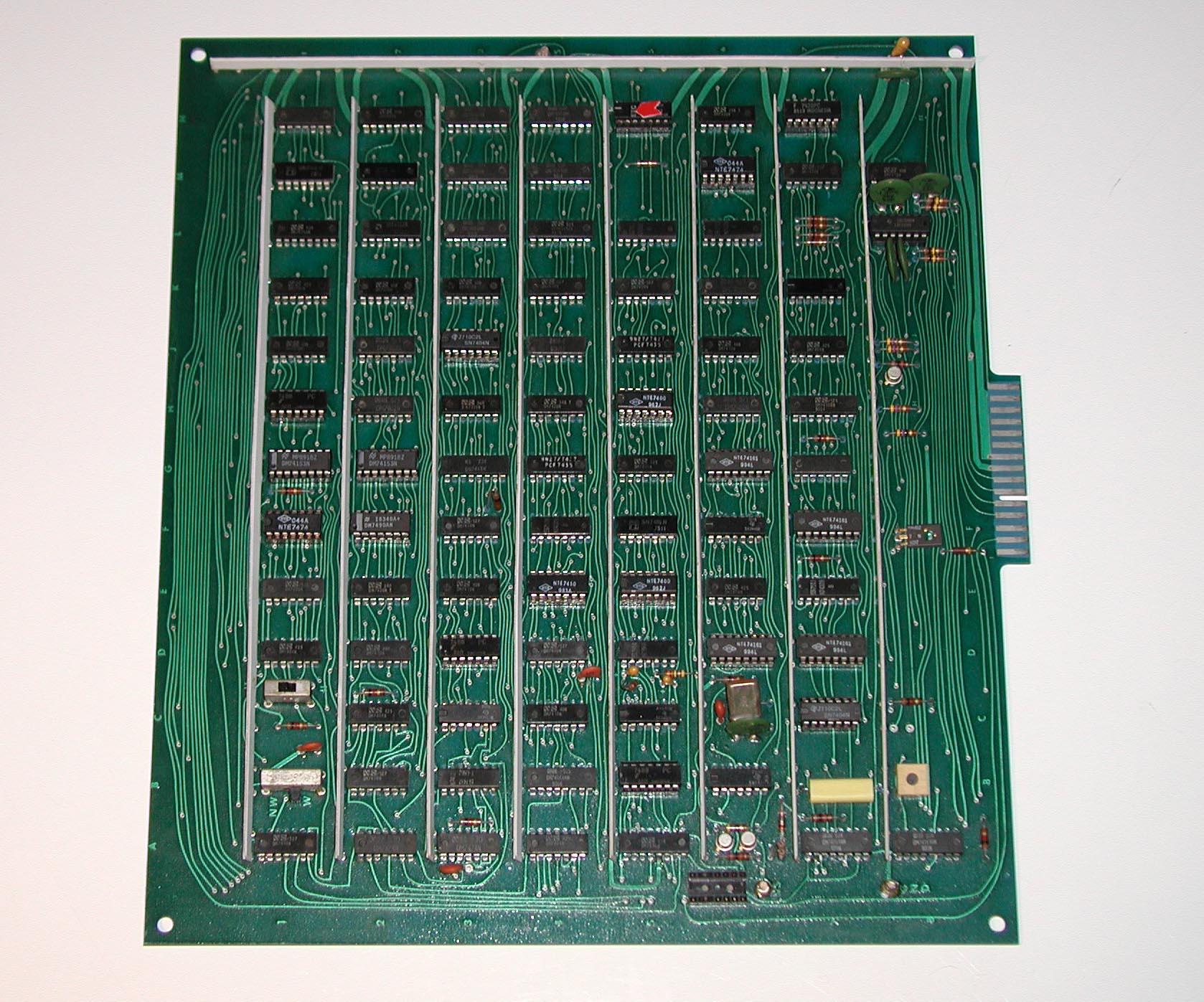
I had to repair mine without schematics or a manual - one appears to have never been scanned to a pdf.
Here are my notes, in case someone needs them.
The board is marked on the back (circuit side) with the following:
AS1001 JAN-75
REV C
SER [serial number written here mine is 2011]
There are two switches on the game board. One marked (11 and 15) controls the score at which the game ends. The other, marked (NW - W) - I can't remember what it does. There is also a small POT on the board - don't know what it does either.
Pinouts
| Pin | Wire color | Function |
|---|---|---|
1 |
Green |
Coin Switch |
2 |
Yellow |
Coin Switch |
3 |
Purple |
Player / Computer Switch? |
4 |
Gray |
Player Control POT - Right Bottom |
5 |
Brown |
Player Control POT - Right Top |
Key |
||
6 |
Orange |
Player Control POT - Left Top |
7 |
Pink |
Player Control POT - Left Bottom |
8 |
Orange, White, White |
Ground |
9 |
Red x2 |
+5v DC |
10 |
Yellow |
? |
11 |
Black |
Free Game LED |
12 |
Red |
Free Game LED |
13 |
Pink |
Video Input |
14 |
Yellow |
Start Game Button |
15 |
Orange |
Audio Out (to Monitor for Amplification) |
Motorola XM501 Monitor - Molex Pinout
| Pin | Wire Color | Function |
|---|---|---|
1 |
Pink |
Video Input |
2 |
- |
- |
3 |
White x2 |
DC Ground |
4 |
Orange |
Audio Input |
5 |
Green |
Audio Out (to Speaker) |
6 |
Red x2 |
+5v DC Output to game PCB |
7 |
Light Green |
AC Common
Ground |
8 |
Green / White |
Audio Out (to Speaker) Paint Dot Side |
9 |
Purple |
AC Low |
10 |
Gray |
AC High |