Differences Between Targ & Spectar Color Adapter Boards:
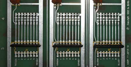
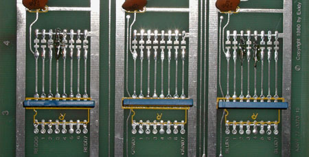
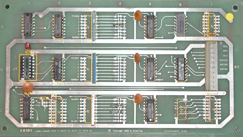
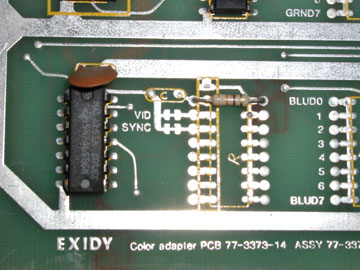
The Video PCB used for Targ and Spectar are the same exact board with additional modifications made to the Spectar board to change a few colors (jumpers at 4A & 4C) and some have been changed to add composite blanking (wire patch on bottom of board from pin 2 of J1 at 1B to pin 7 of 74LS151 at 5C, trace cut between pin 7 & 8 at 5C [photo]).
Targ color adapter boards can be used with a Spectar PCB, but the colors will be wrong- most noticeably the maze walls will be yellow instead of green.
Spectar color adapter boards that have the wire patch to add composite blanking will not display blue when used with Targ PCBs, since Targ boards don't send anything to this output and this lack of signal affects the blue output of the 74LS151 at 5C.
Spectar color adapter boards that don't have this patch when hooked up to a Targ PCB display Spectar colors- the maze walls will be green instead of yellow.
Summary of How the Board Works:
The Spectar manual contains an excellent description of each of the game's PCBs. Here's a summary of my understanding of how the color adapter board functions:
- The video signals enter the PCB from the motherboard via a 14-pin DIP ribbon cable to the socket at 1B.
- The hex value of the character to be displayed is divided into 4 equal segments in the 74LS74 at 1A. Each of these segments has its own priority code and color determined by jumpers at 4A (Red), 4B (Green), 4C (Blue).
- The decoder 74LS139 at 2A merges the composite video signal with the output from 1A.
- The 74LS148 prioritizes which element is to be displayed at that screen position: Moving Object 1, Moving Object 2, or the character from character RAM.
- The three 74LS151 color multiplexers at 5A, 5B, 5C output each separate RGB color from the color jumpers based on the priority code.
- The color info goes to the 74LS86 at 6A that allows for output video to be negative true if a jumper at 2C is cut.
- The sync info goes to the 74LS86 at 1C that allows for sync video to be negative true if a jumper at 2C is cut.
- Final video is output to the monitor from the 74LS174 at 6B.
Color is determined by jumpers at 4A (Red), 4B (Green), 4C (Blue). Unconnected jumpers add color (the white squares below):
 |
|
 |
| Targ Color Adapter |
|
Spectar Color Adapter |
| Jumper Line |
Red |
Green |
Blue |
Resulting Color |
|
Jumper Line |
Red |
Green |
Blue |
Resulting Color |
| 0 - Background |
|
|
|
Blue |
|
0 - Background |
|
|
|
Blue |
1 - Character RAM
($00 - $3F) |
|
- |
- |
Red |
|
1 - Character RAM
($00 - $3F) |
|
- |
- |
Red |
2 - Character RAM
($40 - $7F) |
- |
|
|
Cyan |
|
2 - Character RAM
($40 - $7F) |
|
|
- |
Yellow |
3 - Character RAM
($80 - $BF) |
|
|
- |
Yellow |
|
3 - Character RAM
($80 - $BF) |
- |
|
- |
Green |
| 4 - Character RAM ($C0 - $FF) |
- |
|
|
Cyan |
|
4 - Character RAM
($C0 - $FF) |
|
|
- |
Yellow |
| 5 - Unused |
- |
|
|
Cyan |
|
5 - Unused |
- |
|
|
Cyan |
6 - Player's Missile
(Moving Object 2) |
|
|
|
White |
|
6 - Player's Missile
(Moving Object 2) |
|
|
|
White |
7 - Player's Ship
(Moving Object 1) |
- |
|
- |
Green |
|
7 - Player's Ship
(Moving Object 1) |
|
|
- |
Yellow |
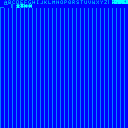
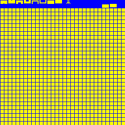
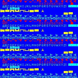
Targ Test ROM Video Tests
The Targ Test ROM's video tests send known signals to the color adapter board which can be used with a logic probe to isolate problems.
Targ Test ROM
Video Test 1: |
Targ Test ROM
Video Test 2: |
Targ Test ROM
Video Test 3: |

74LS74 (1A)
pin 5 = Low
pin 9 = Low
74LS139 (2A)
pin 4 = Pulsing
pins 5,6,7 = High
74LS148 (2B)
pins 6,7 = High
pin 9 = Pulsing
74LS151
Red (5A) pin 5 = Pulsing
Green (5B) pin 5 = Low
Blue (5C) pin 5 = Pulsing
74LS86 (6A)
pin 3 = Pulsing
pin 6 = Low
pin 8 = Pulsing
74LS174 (6B)
pin 2 = Pulsing
pin 5 = Low
pin 7 = Pulsing
|
74LS74 (1A)
pin 5 = Low
pin 9 = High
74LS139 (2A)
pin 5 = Pulsing
pins 4,6,7 = High
74LS148 (2B)
pins 6,9 = High
pin 7 = Pulsing
74LS151
Red (5A) pin 5 = Low
Green (5B) pin 5 = Pulsing
Blue (5C) pin 5 = High
74LS86 (6A)
pin 3 = Low
pin 6 = Pulsing
pin 8 = Low
74LS174 (6B)
pin 2 = Low
pin 5 = Pulsing
pin 7 = Low
|
74LS74 (1A)
pin 5 = High
pin 9 = Low
74LS139 (2A)
pin 6 = Pulsing
pins 4,5,7 = High
74LS148 (2B)
pins 6 = High
pin 7,9 = Pulsing
74LS151
Red (5A) pin 5 = Pulsing
Green (5B) pin 5 = Pulsing
Blue (5C) pin 5 = Pulsing
74LS86 (6A)
pin 3 = Pulsing
pin 6 = Pulsing
pin 8 = Pulsing
74LS174 (6B)
pin 2 = Pulsing
pin 5 = Pulsing
pin 7 = Pulsing
|
Targ Test ROM
Video Test 4: |
Targ Test ROM
Video Test 5: |
Targ Test ROM
Video Test 6: |

74LS74 (1A)
pin 5 = High
pin 9 = High
74LS139 (2A)
pin 7 = Pulsing
pins 4,5,6 = High
74LS148 (2B)
pins 7,9 = High
pin 6 = Pulsing
74LS151
Red (5A) pin 5 = Low
Green (5B) pin 5 = Pulse
Blue (5C) pin 5 = High
74LS86 (6A)
pin 3 = Low
pin 6 = Pulsing
pin 8 = High
74LS174 (6B)
pin 2 = Low
pin 5 = Pulsing
pin 7 = High
|
|

74LS74 (1A)
pin 5 = Low
pin 9 = Low
74LS139 (2A)
pins 4,5,6, 7 = High
74LS148 (2B)
pins 6,7,9 = High
74LS151
Red (5A) pin 5 = Low
Green (5B) pin 5 = Low
Blue (5C) pin 5 = High
74LS86 (6A)
pin 3 = Low
pin 6 = Low
pin 8 = High
74LS174 (6B)
pin 2 = Low
pin 5 = Low
pin 7 = High
|
Targ Color Adapter PCB:
Issues using monitors requiring composite sync
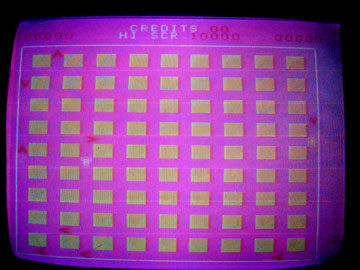
A visitor described a problem with their Targ where the blue background was black and other game colors were incorrect.
They were using a newer replacement monitor that required composite sync. The Targ Color Adapter PCB outputs horizontal and vertical sync separately and they had combined these outputs into one "composite" sync input for the new monitor.
The Color Adapter PCB's monitor output does have a composite marking, but I'm unsure if it's active.
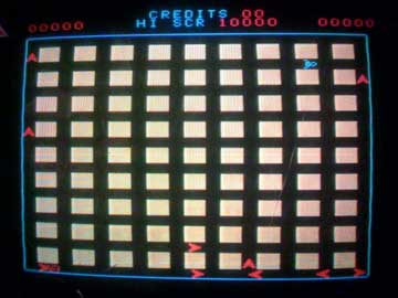
I was told the problem was remedied only by using an older monitor that had inputs for horizontal and vertical sync.
Without further testing, I'm not sure if it's possible to properly hook a Targ Color Adapter PCB to newer monitors.


![[photo]](_images/spectar_composite_blanking.jpg)