Outerworld Arcade Outerworld Arcade

Cinematronics Sound Board Repair:
Star Castle

First Steps to Repair a Dead Star Castle Sound Board:

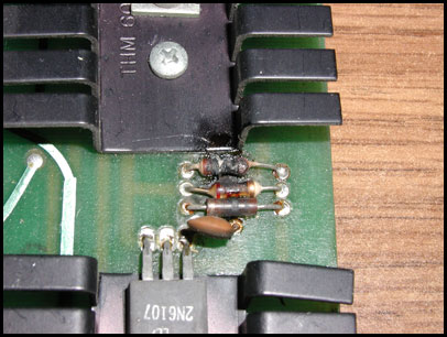
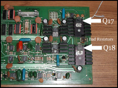
  1. Visually inspect the board for damage - particularly in the area of R122. If resistors are burnt, test and replace bad speaker drive transistors and burnt resistors before applying power to the board again.
  2. Confirm your speaker is good. A bad sound board can and will kill a speaker.
  3. Check the voltage converters on the board. Replace IC4 or IC5 if their +15v or -15v outputs are significantly off.

Testing the Speaker Drive Transistors

After searching for a data sheet on these two components I found that Q17 (2N6292) was an NPN transistor, while Q18 (2N6107) was a PNP transistor. With this information in hand, I referenced the following description on testing transistors with a digital multimeter from Appendix D: of The Cinematronics Vector Monitor Repair Guide:

To do this test, the transistor must be removed from the circuit.

Test #1

  1. Set your meter to the diode test.
  2. Connect the red meter lead to the base of the transistor.
  3. Connect the black meter lead to the emitter.

A good NPN transistor will read a JUNCTION DROP voltage of between 0.45v and 0.9v. A good PNP transistor will read OPEN.

Test #2

Leave the red meter lead on the base and move the black lead to the collector. The reading should be the same as the previous test.

Test #3

  1. Reverse the meter leads in your hands and repeat the test.
  2. This time, connect the black meter lead to the base of the transistor.
  3. Connect the red meter lead to the emitter.

A good PNP transistor will read a JUNCTION DROP voltage of between 0.45v and 0.9v. A good NPN transistor will read OPEN.

Test #4

Leave the black meter lead on the base and move the red lead to the collector. The reading should be the same as the previous test.

Test #5

Place one meter lead on the collector, the other on the emitter. The meter should read OPEN.
Reverse your meter leads. The meter should read OPEN. This is the same for both NPN and PNP transistors.

Thanks to Randy Fromm (randyfromm.com) for this excellent summary of the diode test method.

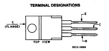
Here is a diagram of which leads are the Emitter, Collector and Base on this type of transistor:

Transistor Diagram

Testing the Speaker:

Testing the Speaker

This test can be done with the speaker in circuit - no need to remove the leads to the speaker.

Switch the multimeter to the Ohms/Continuity test.

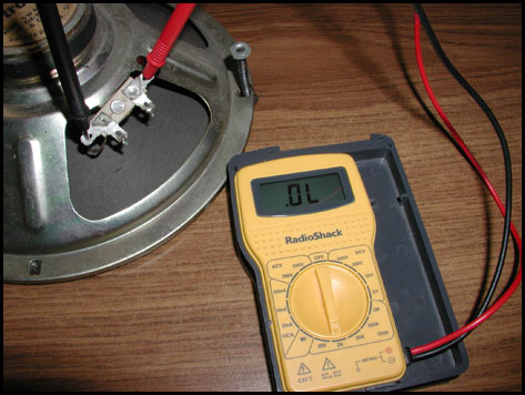
Place multimeter leads on + and - of speaker inputs.

There should be some resistance (some number near zero).

If test shows no change (open circuit) like the speaker in the image above, the speaker is BAD.

Checking for proper voltages on the sound board:

Checking Voltages

Place black probe of multimeter on connector pin 1 of J1 (white connector)

Then place red probe of multimeter on each of the following pins to test for proper voltage:

+5v DC: pin 14 on IC 1: 7414

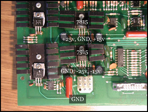
+25v DC: pin 1 of IC 4: 7815
(Higher voltages, such as +30v are OK, so long as they are within the accepted input voltages for the 7815. This voltage is converted to +15v for use in the circuits)

+15v DC: pin 3 of IC 4: 7815

-25v DC: pin 2 of IC 5: 7915
(Higher voltages, such as -30v are OK, so long as they are within the accepted input voltages for the 7915. This voltage is converted to -15v for use in the circuits)

-15v DC: pin 3 of IC 5: 7915

Troubleshooting the Background Drone:

The Star Castle manual table 1 (duplicated below) lists the voltages that should be present at the background sound's DAC, low pass filter, and VCO. Unfortunately it is oddly incomplete, listing information for four of the eight possible background speeds. I took measurements using two good boards and one (#022) that the sounds were a bit too low in frequency.

From looking at the resulting data, the lower frequency sounds look to be caused by the +15 voltage converter, which was outputting 14.5v. R2 converts +15v to +10v, but in this case was only outputting +9.72v. This resulted in lower voltages at pin 5 of the VCO causing the lower frequency background drone.

Star Castle Manual (Table 1)
15v -[R2]- 10v
Background # IC6 (7406)
9-11-13
IC7-6 (TL081)
(DAC)
IC8-6 (TL081)
(Low Pass Filter)
IC9-5 (566)
(VCO)
1 1 1 1 -0v -7.6v -3.2v
2 1 1 0 -1v -6.v -3v
3 1 0 1 -2v -5v -2.6v
4 1 0 0      
5 0 1 1 -4v -3v -2v
6 0 1 0      
7 0 0 1      
8 0 0 0      
Star Castle: F-20-077-284 Rev. C "Good"
15.08v -[R2]- 10.05v
Background # IC6 (7406)
9-11-13
IC7-6 (TL081)
(DAC)
IC8-6 (TL081)
(Low Pass Filter)
IC9-5 (566)
(VCO)
1 1 1 1 -0.19v -7.1v -3.2v
2 1 1 0 -1.21v -6.06v -2.88v
3 1 0 1 -2.24v -5.0v -2.56v
4 1 0 0 -3.27v -3.96v -2.24v
5 0 1 1 -4.26v -2.94v -1.92v
6 0 1 0 -5.29v -1.88v -1.60v
7 0 0 1 -6.33v -0.82v -1.28v
8 0 0 0 -7.35v +0.25v -0.95v
Star Castle: 7-11-077-119 Rev. A "Good"
15.12v -[R2]- 10.19v
Background # IC6 (7406)
9-11-13
IC7-6 (TL081)
(DAC)
IC8-6 (TL081)
(Low Pass Filter)
IC9-5 (566)
(VCO)
1 1 1 1 -0.15v -7.31v -3.32v
2 1 1 0 -1.20v -6.30v -3.00v
3 1 0 1 -2.23v -5.29v -2.69v
4 1 0 0 -3.29v -4.27v -2.37v
5 0 1 1 -4.36v -3.22v -2.05v
6 0 1 0 -5.42v -2.19v -1.73v
7 0 0 1 -6.46v -1.17v -1.41v
8 0 0 0 -7.50v -0.14v -1.08v
Star Castle: CT-14-077-022 Rev. B "frequencies too low"
14.53v -[R2]- 9.72v
Background # IC6 (7406)
9-11-13
IC7-6 (TL081)
(DAC)
IC8-6 (TL081)
(Low Pass Filter)
IC9-5 (566)
(VCO)
1 1 1 1 -0.33v -6.33v -2.97v
2 1 1 0 -1.4v -5.5v -2.7v
3 1 0 1 -2.3v -4.6v -2.4v
4 1 0 0 -3.3v -3.7v -2.2v
5 0 1 1 -4.2v -2,9v -1.9v
6 0 1 0 -5.2v -1.9v -1.6v
7 0 0 1 -6.1v -1.0v -1.3v
8 0 0 0 -7.2v -0.1v -1.05v

Repair Logs:

Sound Board #1: 7-11-077-119 Rev A.
Initial Status: Damaged Components

Handwritten tag stated that board was repaired on 12-15-1981 for $74.84. Had "Southwest" on tag: not sure if this was repair house or operator name. Three ICs had been replaced with sockets added: IC1(7414), IC6(7406), and IC12(74LS393).

IC25 had also been replaced at some point, this one without a socket.

Visual inspection showed resistor R122 was fried. Resistors R123 & R124 looked like they had taken some heat as well.

Burnt Resistors Power Transistors Locations

Looking at the schematics in the Star Castle manual, I could see that these resistors are in the final amp section of the board. From my experience with the Cinematronics monitors, I know that fried resistors can be caused by a transistor going bad. We need to check and replace any bad transistors before replacing the resistors. There are two in this part of the board, Q17 (2N6292) and Q18 (2N6107).

WARNING:
If your board looks like this, the bad transistors also probably fried your speaker. See below for how to test your speaker. Don't try plugging it into other cabinets or speakers to test it. Until the board is repaired, IT WILL KILL ANY SPEAKER HOOKED UP TO IT.

After testing the two transistors, I found the following:

Q17 (2N6292) - NPN
Test #1 showed OPEN - it should read between 0.45v and 0.9v on a NPN transistor- this showed the transistor was BAD.

Q18 (2N6107) - PNP
Passed all tests except test #5 - the test read 0v - shorted (same as just touching the two probes together) and should read OPEN- this showed the transistor was BAD.

If parts in your board have been replaced with NTE parts:
NTE196 crosses to 2N6292
NTE197 crosses to 2N6107
NTE857M crosses to TLO81

After installing a new 2N6292 and 2N6107, I plugged it in and heard - nothing.
Checked voltages - all good.
I checked to see if the speaker was good. The speaker tested as BAD.
Plugged in a good speaker and voila! - Star Castle sounds!

IC15 (TL081) was later socketed and replaced due to problems with the noise circuit.

Sound Card #2: Rev B
Initial Status: No Sounds

There was no physical damage to the board, but did the transistor test on Q17 and Q18 as described above (removing them from the circuit to do so). Both transistors tested GOOD.

Checked for proper voltages on the board. All voltages on the board tested good.

When I tested the speaker found it was BAD. After plugging in this board again with a good speaker I got Star Castle sounds!

The board was missing the thrust and explosion sounds which were fixed by replacing C30 and C34.

Fireball sound stuck "ON" (07/23/2007). The sound board started playing the "fireball" sound constantly whenever the machine was on. After pulling the board and using a logic probe on IC1, a 7414 (Hex inverter with schmitt-trigger inputs), I found that pin 2 was stuck low. The input of pin 1 was low and thus the output of pin 2 should have been high. I replaced the 7414 with a new one (and added a socket for good measure) and the problem was fixed.

Sound Card #3: F-20-077-284 Rev. C
Initial Status: Missing and Loose Parts

C36 (334K 100v) Film capacitor was missing. Used in the thrust circuit. Part was replaced.

C17 (100uf) was loose. Used in the noise circuit. Part was resoldered.

7815 Voltage Regulator was bad and there was a short in the +15v circuit. Cut legs off ICs in the circuit until I found the short. IC19 (CA3080) was the culprit, used in the loud explosion circuit. Socketed and replaced it and repaired cut legs. Replaced both 7815 and 7915 regulators.

There seems to be some distortion in the noise circuit. The output of the noise chip IC14-3 is 0v-14v rather than 0v-11.5v as described in the manual. The waveform at IC15-6 is centered on ground as it should be.

Sound Card #4: F-20-077-284 Rev. B
Initial Status: Star sound was intermittently changing, Background drone frequency too low

Star Sound: Capacitor C37 had one leg that had broken free from the PCB. The connection was intermittent. Reflowing and adding a bit of new solder to the connection fixed the problem.

Background Frequency Too Low: See detail above. +15v voltage regulator was putting out +14.53v which affected the frequency of the background VCO.