

Pricing
Control Panel Distribution PCB: $35.00, 2 or more: $30.00 each
USPS Priority Mail Small Flat Rate Box Shipping: $10.65
USPS First Class Shipping in a bubble mailer: $6.00
Overview
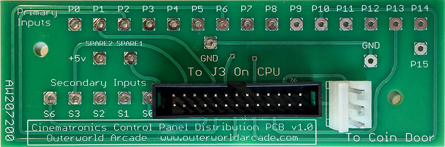
The Cinematronics Control Panel Distribution PCB connects the CPU board to the game's buttons and joysticks on the control panel as well as the coin switches in the coin door. The buttons and joysticks on the control panel are soldered to the distribution PCB corresponding to the inputs (primary or secondary) that are being read by the game's ROM. The coin door is attached to the distribution PCB via a three pin Molex wafer connector.
This reproduction of the original PCB has the following changes:
- In the original PCB, the ribbon cable was permanently attached to the board. The reproduction uses a standard 26-pin box header connector so that a standard ribbon cable can be used to connect between the CPU and the control panel. Because of this, a 30 inch 26-Pin (2x13) Female to Female 2.54mm-Pitch 26-wire IDC Flat Ribbon Cable is required to connect the control panel PCB to the CPU. These can be found on eBay for about $8 shipped.
- The connector change required rerouting the traces on the board, but the mounting holes and all other connection points are in the same locations as in the original board.
- The reproduction PCB includes improved labeling of the inputs and connectors.
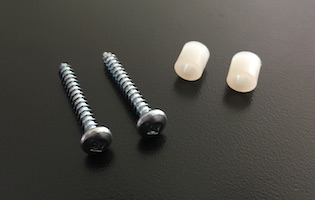
- The original board has two 1/4" metal swage spacers installed. The reproduction uses two included 1/4" nylon spacers for this purpose.
- For mounting the PCB to the underside of the control panel, two square drive pan head screws are included. Except for their finish (zinc rather than painted black), these screws are identical to those used by Cinematronics.
Package Contents
- (1) Control Panel Distribution PCB
- (2) 1/4" Nylon Spacers
- (2) Square Drive Pan Head Screws
Ordering Information
Availability (2/2025): In Stock.
Please contact me with any questions or to purchase a board.
Wiring Examples
Below are examples of control panel wiring to the distribution PCB.
|
Control Panel Distribution PCB Wiring |
|||
|---|---|---|---|
| CPU PCB J3 pins |
Control Panel PCB Connections |
Function | Wire Color |
| 11 | P0 | One Player Start | Brown |
| 9 | P2 | Two Player Start | Red |
| 13 | P6 | Left | Orange |
| 19 | P8 | Right | Yellow |
| 17 | P10 | Forward / Shield | Green |
| 20 | P12 | Fire | Blue |
| 26 | Ground | Black | |
|
Control Panel Distribution PCB Wiring |
|||
|---|---|---|---|
| CPU PCB J3 pins |
Control Panel PCB Connections |
Function | Wire Color |
| 11 | P0 | Player Two: Left | White / Green |
| 10 | P1 | One Player Start | Brown |
| 9 | P2 | Player Two: Right | Red |
| 8 | P3 | Two Player Start | Orange |
| 15 | P4 | Player Two: Forward | Yellow |
| 14 | P5 | Player Two: Fire | Green |
| 20 | P12 | Player One: Left | Blue |
| 21 | P13 | Player One: Fire | Violet |
| 22 | P14 | Player One: Right | Gray |
| 23 | P15 | Player One: Forward | White |
| 26 | Ground | Black | |