All black & white Cinematronics vector games used power supplies that supplied AC voltages and three DC voltages to the game PCBs and monitor. Because of this, swapping in a switching power supply is not possible as it is with other games of the era. If the one in your machine isn't working, it must be repaired.
Three different companies sold power supplies to Cinematronics during this era. Xentek (older titles), Datapower and Condor (newer titles). Vectorbeam used Xentek power supplies, but with a different pinout than the power supplies manufactured for Cinematronics.
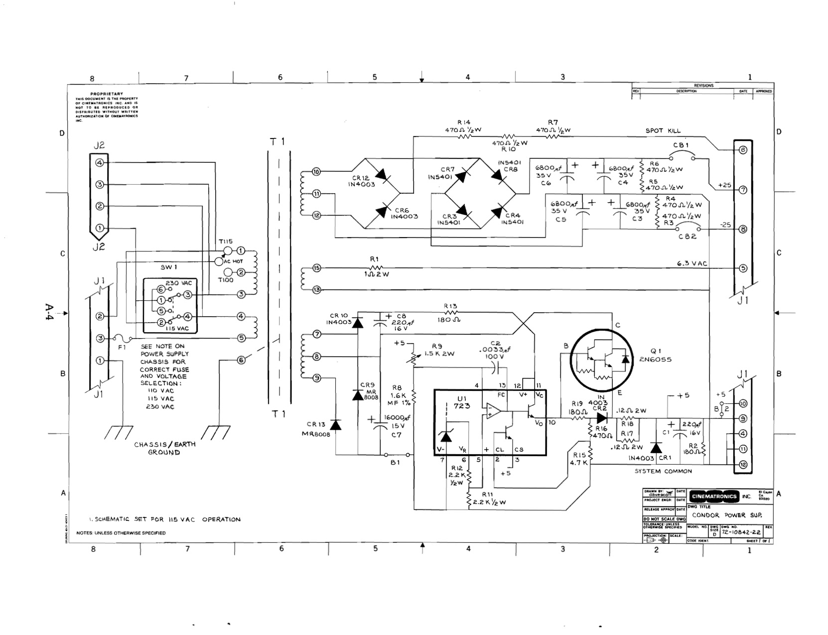
All power supplies, except those that are Vectorbeam labeled, mount exactly the same in each cabinet and have the same pinouts, thus they are interchangeable as needed.
Below you'll find more info about reconditioning each power supply. Click on any image to see a larger version.
Power Supply Pinouts
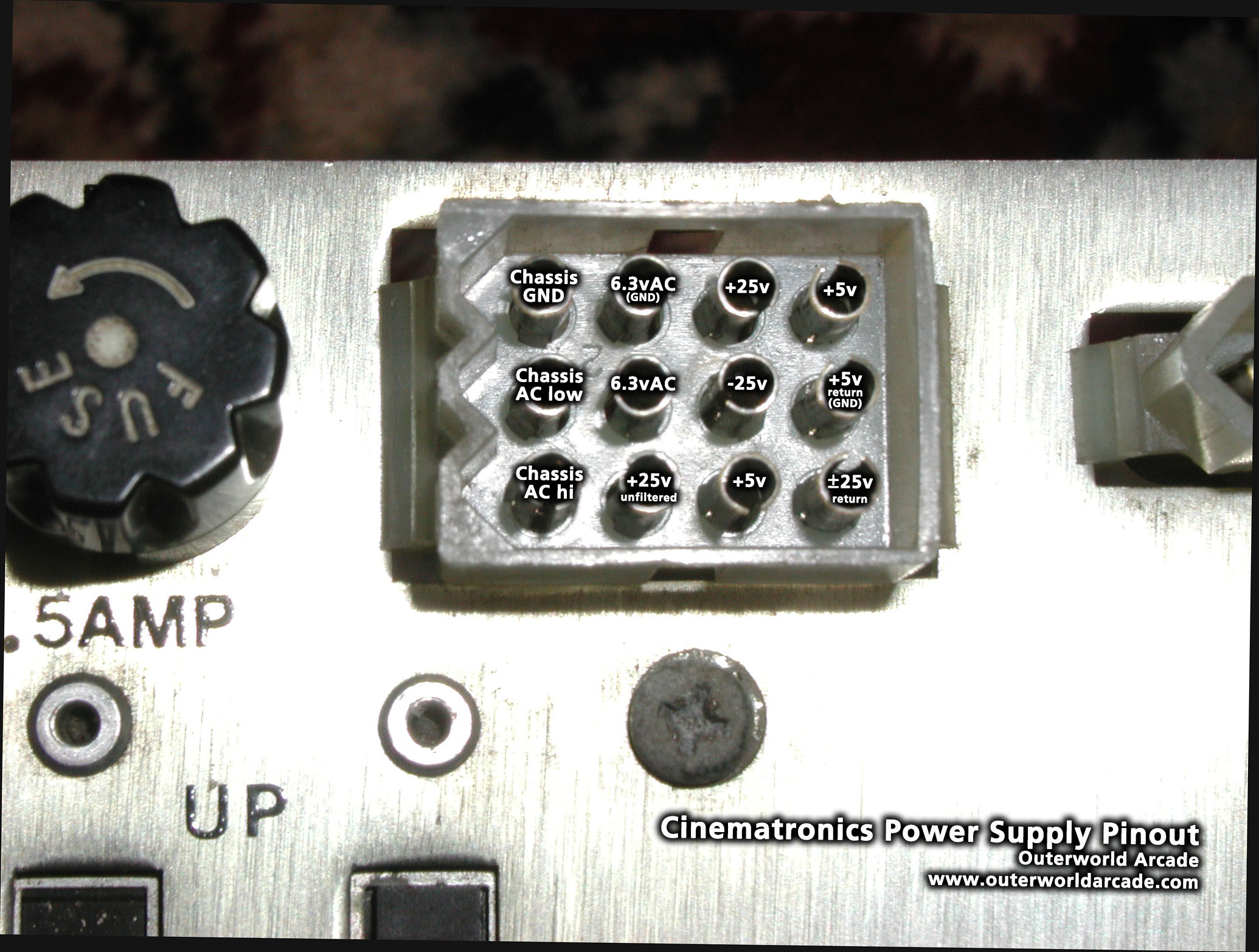
Cinematronics 12-pin (All Manufacturers)
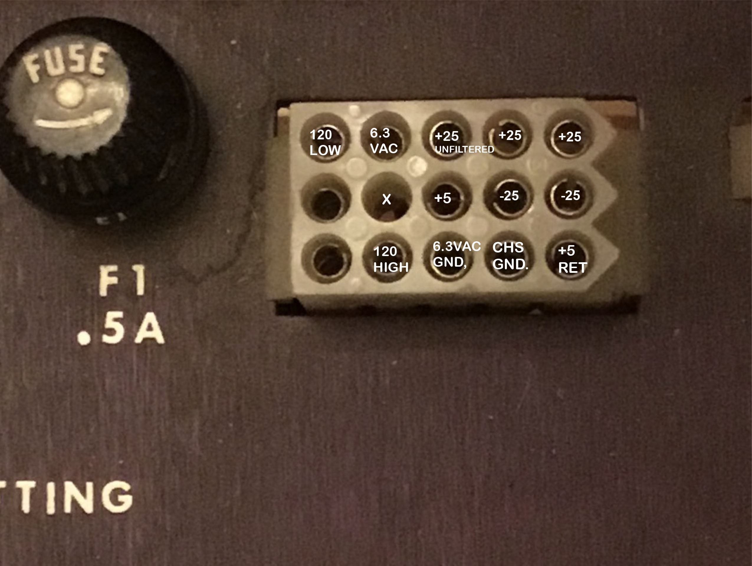
Vectorbeam 15-pin (photo courtesy of Trevor Brown)
Measuring and Adjusting DC Voltages
Each power supply provides three DC voltages to the game's sound board and monitor. These voltages are +5v, +25v, -25v. The CCPU requires only +5v and GND to be connected to operate.
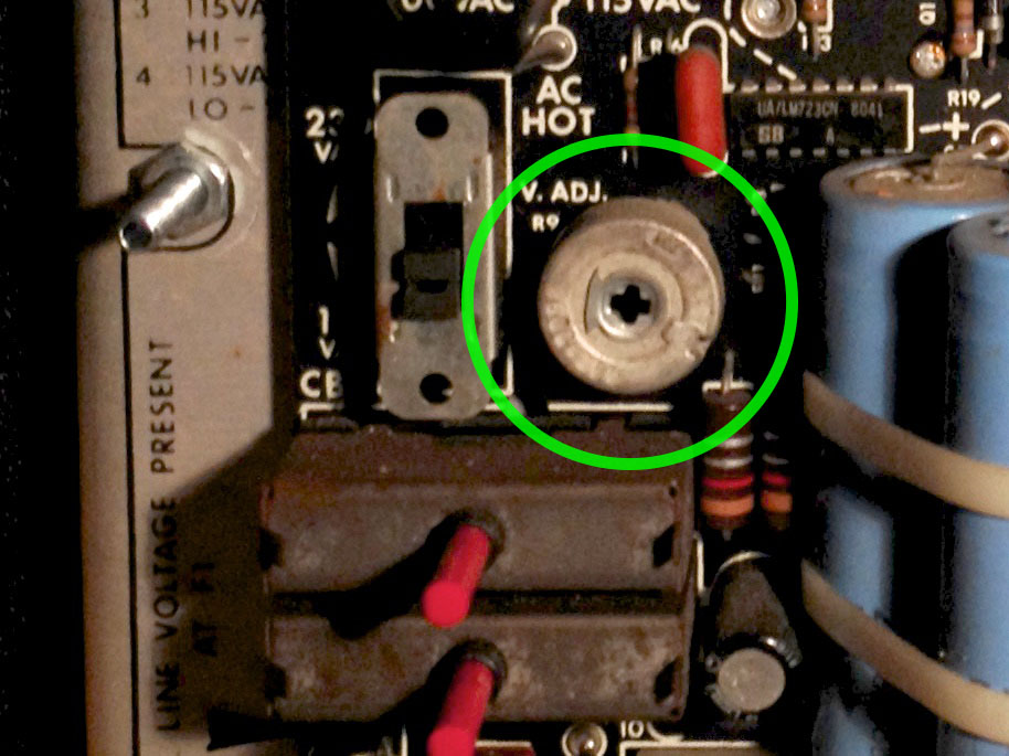
The +5v can be adjusted via a potentiometer located in different places on each power supply. The voltage can be tested at the power supply connection without a load to get a rough idea of the operating status of the unit. If the voltage is 0v or far from +5v, or if some other problem is noticed, the power supply should not be connected to other boards until the problem is resolved.
The +5 voltage is best fine-tuned under load with the CCPU connected, testing at the connector to the CCPU and possibly also at chips on the board. The voltage can drop under load and after the connectors between the power supply and the CCPU and it can be good to confirm the board itself is getting the proper voltage. Keep in mind that the +5 voltage is also used by the monitor and the sound board. You don't want to overpower any of the other boards trying to get +5.0v to a chip on the CCPU.
See the images in each section below for the location to adjust the +5 voltage.
When measured, the +25v and -25v are normally higher than these values. These voltages are stepped down to +15v and -15v on the sound board and monitor. Looking at a typical datasheet for these regulators, the maximum input voltage is around plus or minus 35 volts, minimum is plus or minus 23 volts. As long as the voltage is within this range the voltage regulators should function correctly.
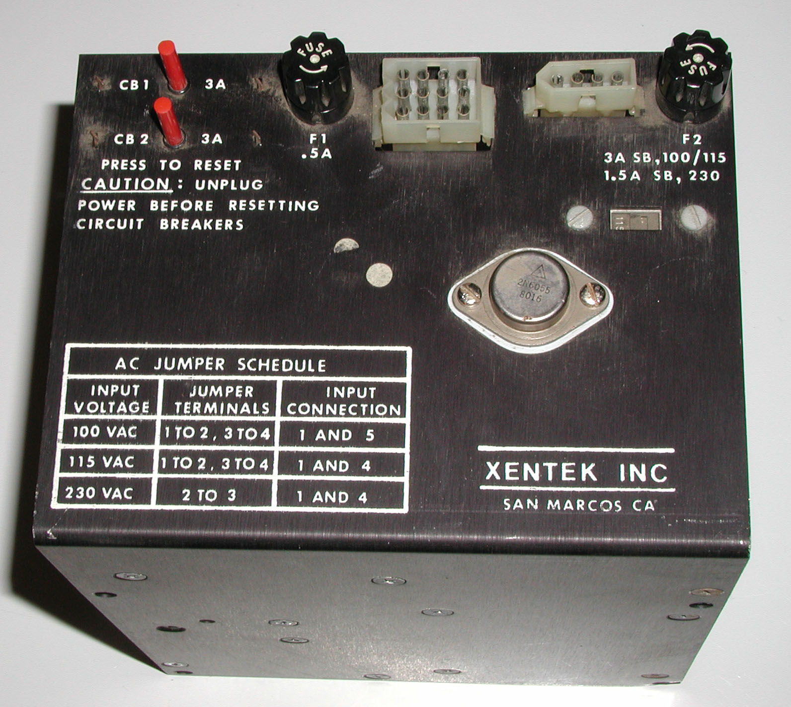
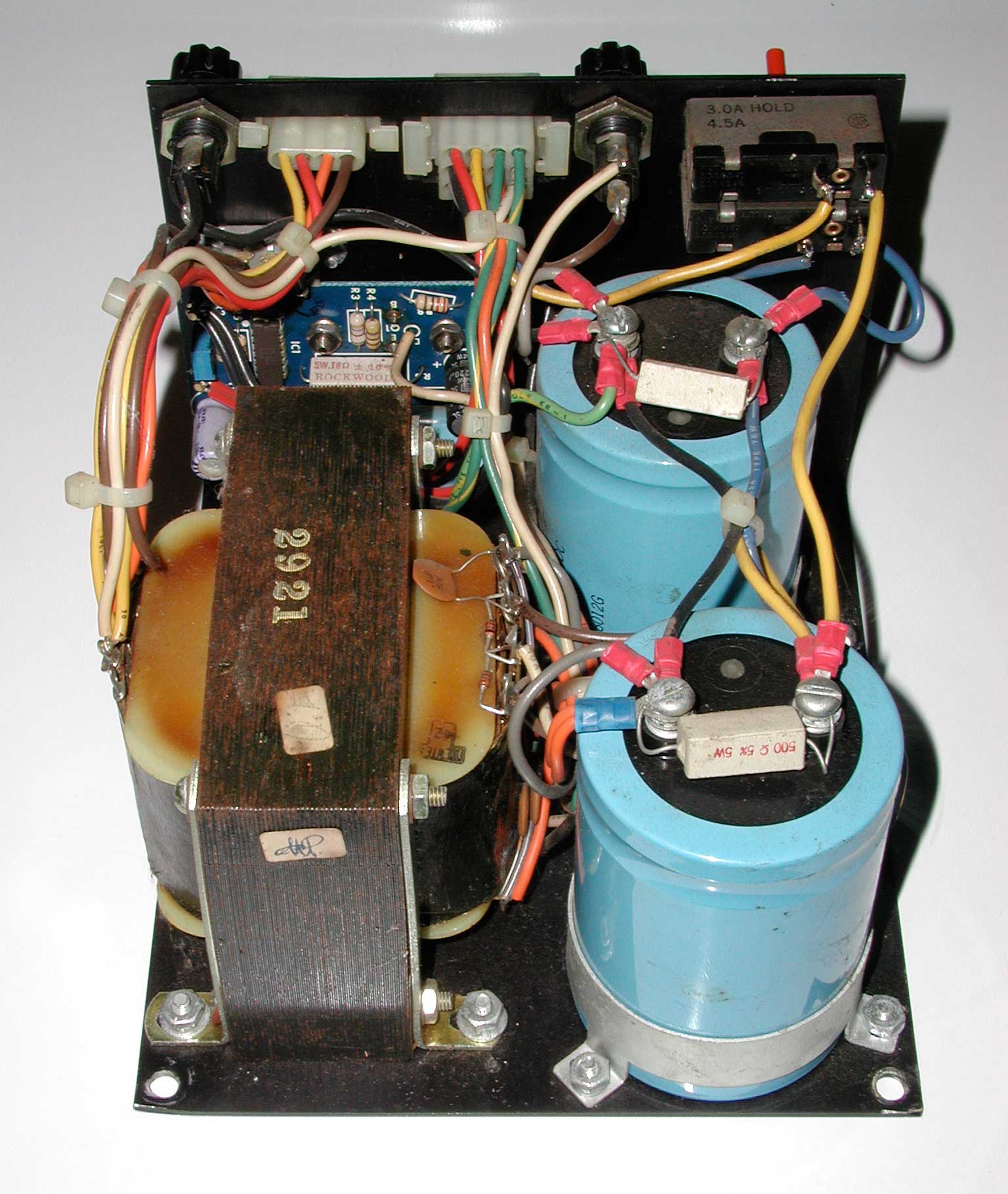
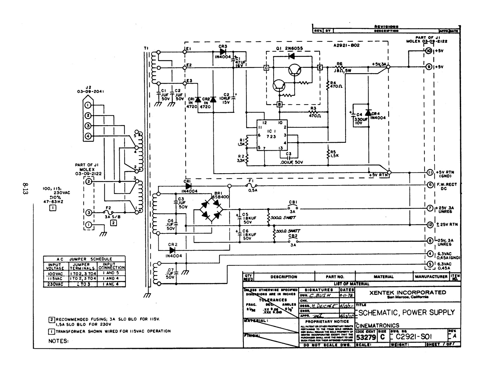
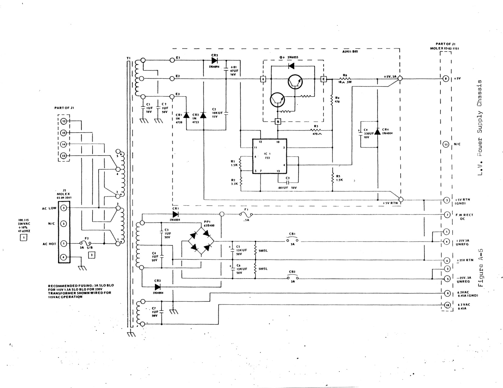
Xentek Power Supply
These power supplies seem to be the most challenging to recondition primarily due to the difficulty in removing the PCB from the power supply chassis. There are multiple issues to overcome in removing the board:
- The 2N6055 (NTE243) mounted to the top of the chassis is soldered to the PCB board underneath.
- There are multi-part spacers that come loose when the 2N6055 is removed.
- Wires connected to the PCB are soldered directly to the board - no in-line connector
Capacitor Info:
| Location | Capacitor | Type |
|---|---|---|
| C1 | 220uf 16v | Radial |
| C2 | 10,000uf 15v | Axial |
| C4 | 330uf 10v | Radial |
Schematics (Xentek Branded):
Schematics (Vectorbeam Branded):
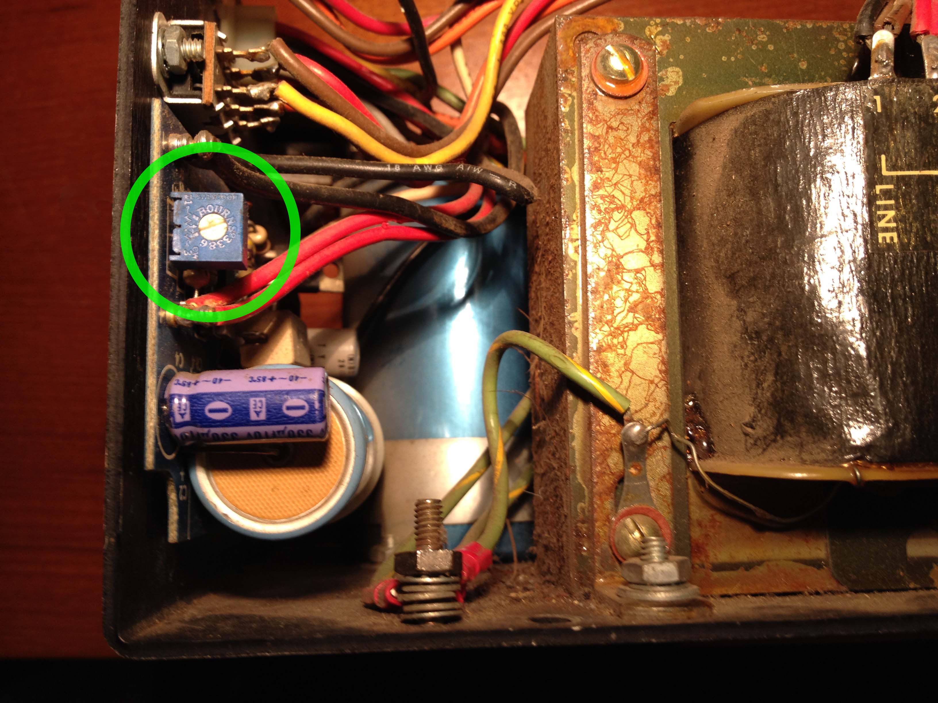
+5v Adjustment:
Some Xentek power supplies have a +5 adjustment, while others do not.
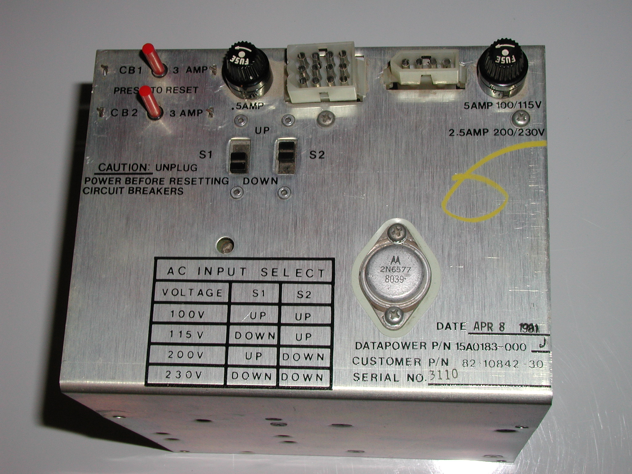
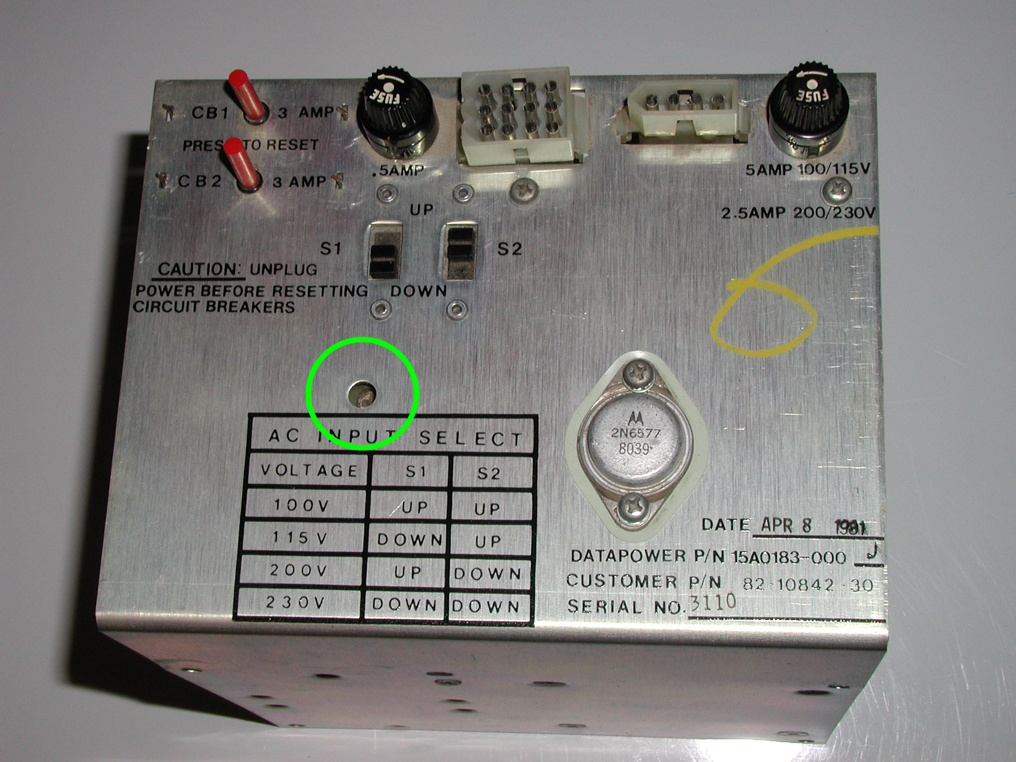
Datapower Power Supply
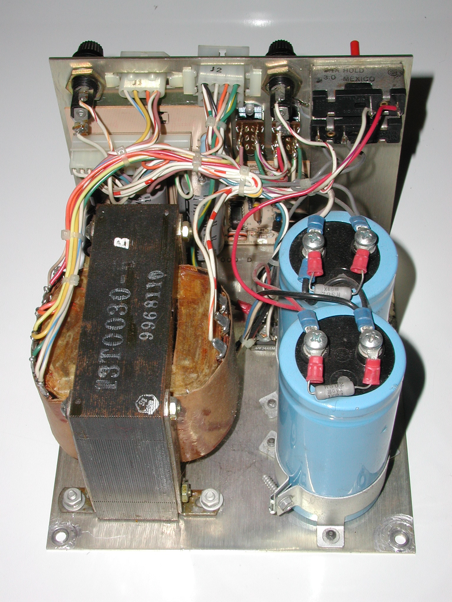
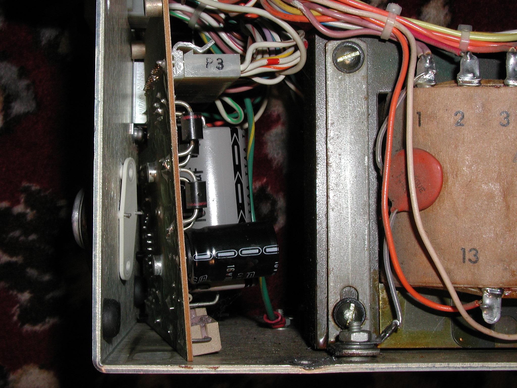
These power supplies are much easier to recondition. Removing the PCB is a three part process:
Step 1: Remove the Power Transistor
The 2N6577 (NTE249) mounted on the top of the chassis is socketed and can be unscrewed and easily removed. There is a plastic spacer between the chassis and the PCB board to be saved when the 2N6577 is removed.
Step 2: Remove the plastic connector from the PCB board.
Step 3: Remove the PCB
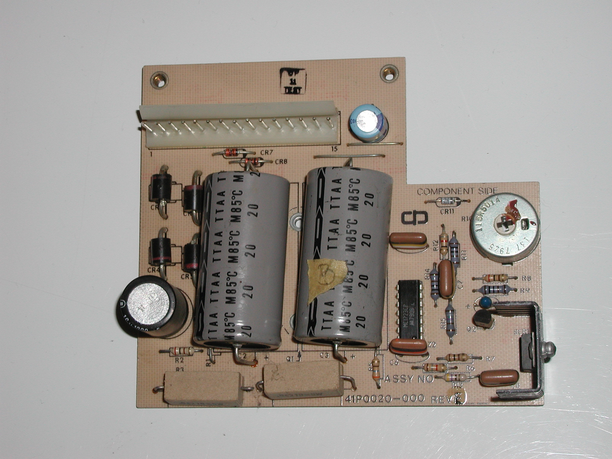
Remove the PCB from the spacers holding the board to the chassis. When removed the board will look like the image above.
Repair Log:
+5v power supply readings with a multimeter were normal without PCB connected but were low (under +1v) with PCB connected. After pulling the power PCB found cracked solder joints on the connector header pins. Re-flowed the solder and the power supply worked perfectly!
Capacitor Info:
| Location | Capacitor | Type |
|---|---|---|
| C1 | 1,000uf 16v | Radial |
| C2 | 10,000uf 16v | Axial |
| C3 | 10,000uf 16v | Axial |
| C9 | 100uf 16v | Radial |
Schematics:
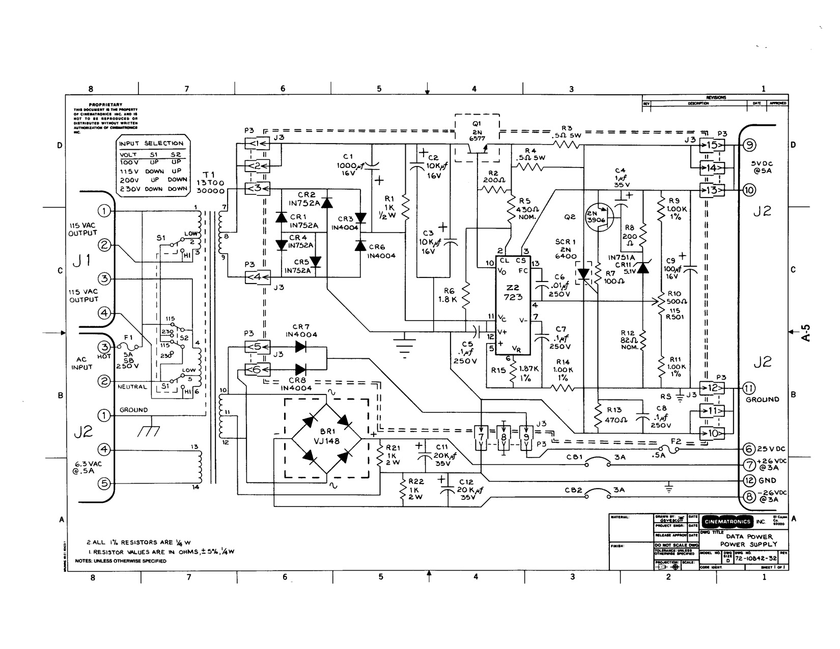
+5v Adjustment:
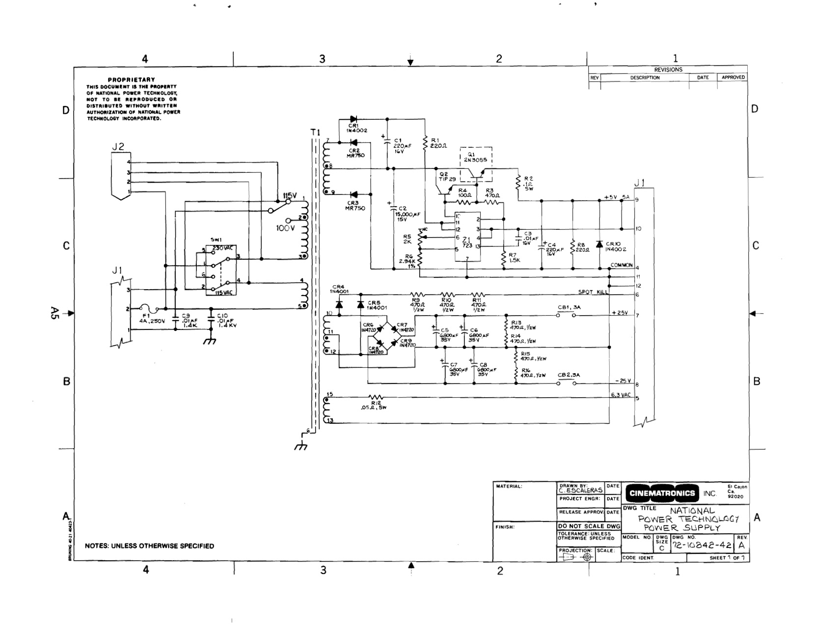
National Power Technology Power Supply
Link to image on the KLOV forums.
Schematics:
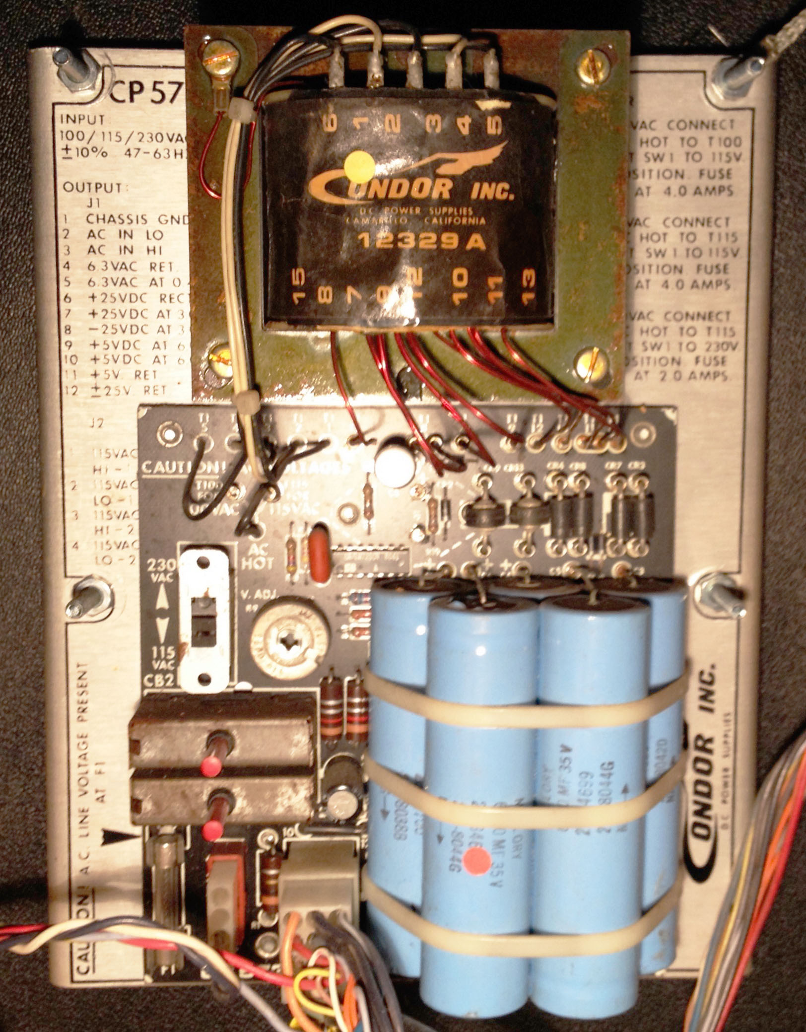
Condor Power Supply
Schematics:
+5v Adjustment: